V nedeljo, 17. maja 2026 bo Marija Mojca Pungerčar v svojem ateljeju s priložno razstavo predstavila gostovanje projekta Sporočilo izgubljeni polovici v New Yorku. Predstavitev bo trajala od 18.00–20.00 ure.
Marija Mojca Pungerčar is visiting New York with the project Message to the Lost Half. In April, she will present the project at the Sunnyside Rhythm Block cultural event.
Marija Mojca Pungerčar gostuje s projektom Sporočilo izgubljeni polovici v New Yorku. Aprila se bo s projektom predstavila na kulturnem dogodku Sunnyside Rhythm Block.
Marija Mojca Pungerčar je od 3. 10. 2025 – 30. 10. 2025 s projektom Singer na razstavi Mesta žensk Arhivi v ospredju. Predstavila se v družbi umetnic Coco Fusco, Larisse Sansour in Sørena Lind, Sanje Iveković ter Stefanie Seibold. Kustosinja razstave je bila Iva Kovač.
Novičnik za samozaposlene v kulturi / KUD Trivia je poslal Ministrstvu za kulturo poziv za spremembo stališča glede obveznega prispevka za dolgotrajno oskrbo.
Novičnik za samozaposlene v kulturi je na YouTube objavil dva nova podkasta: Samozaposlene kulturne ustvarjalke in socialne ter delavske pravice ter Izdajanje računov za samozaposlene v kulturi.
Urednica Novičnika Marija Mojca Pungerčar se je pogovarjala z odvetnico Sandro Cico in računovodjo Barbaro Čuk Krevh. Vabljeni k poslušanju! more »
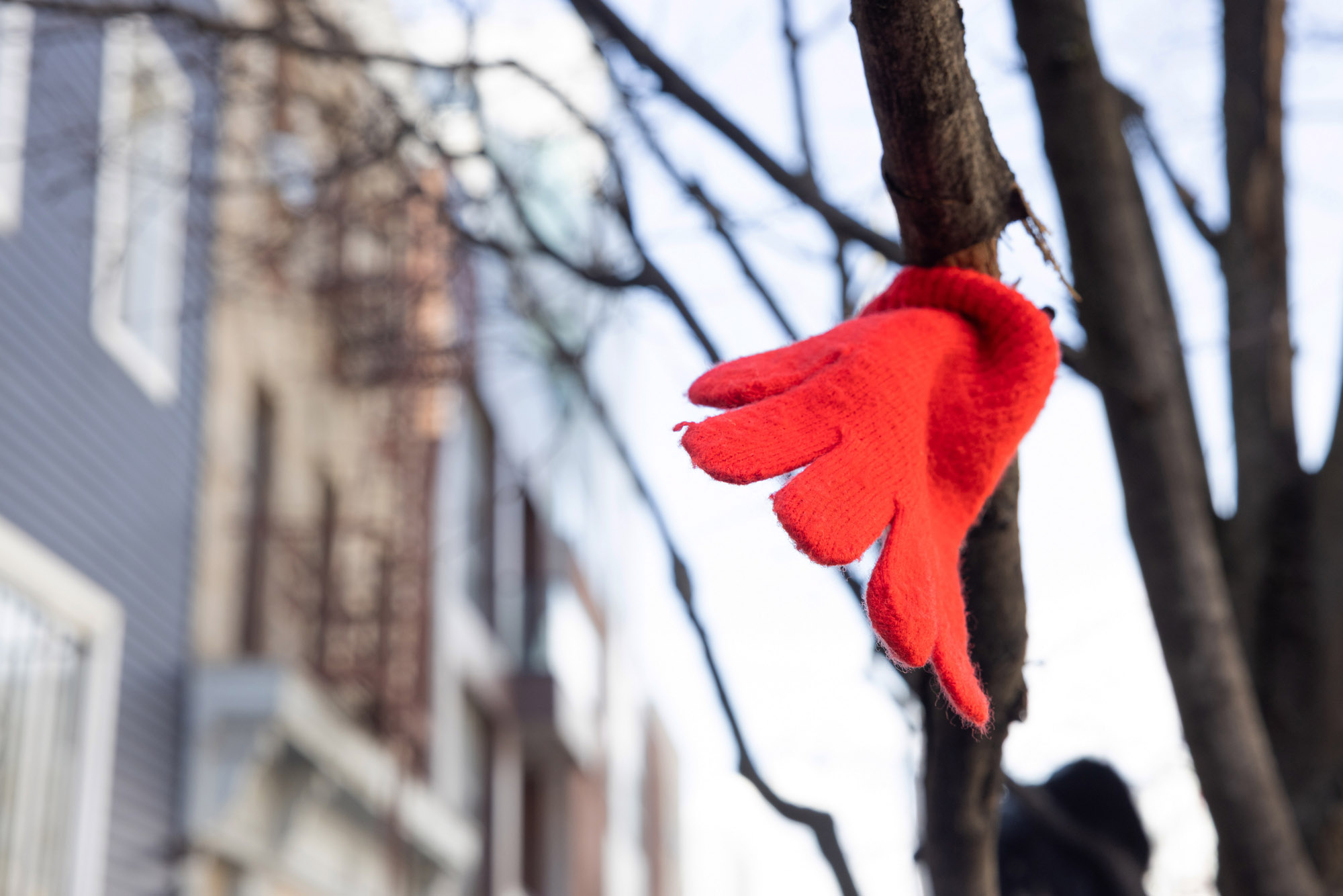
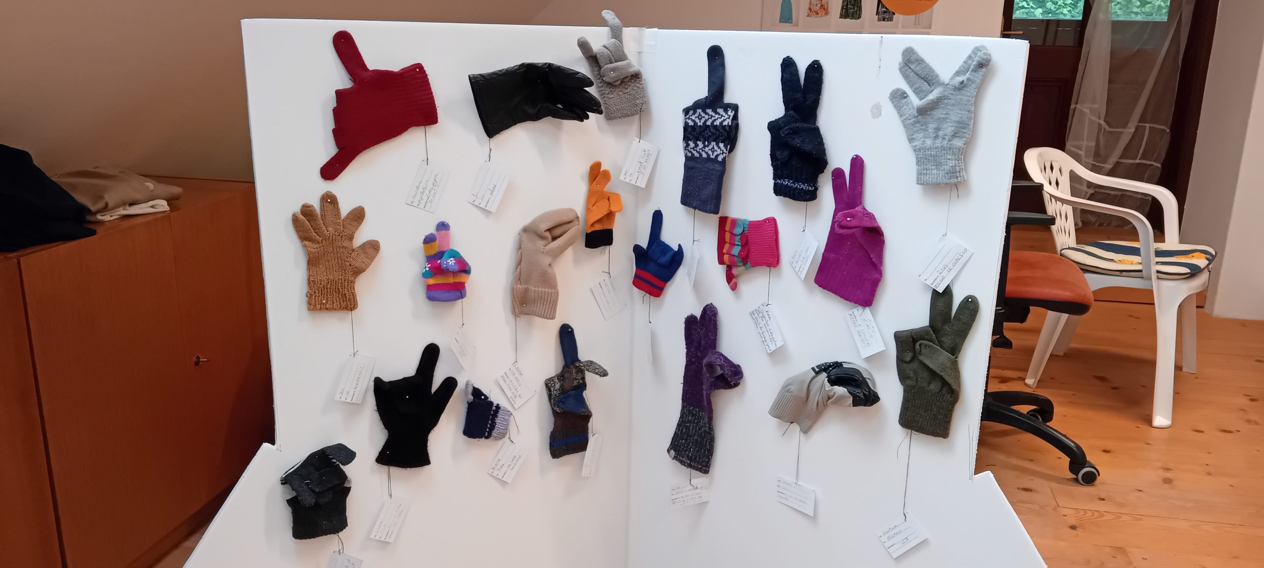
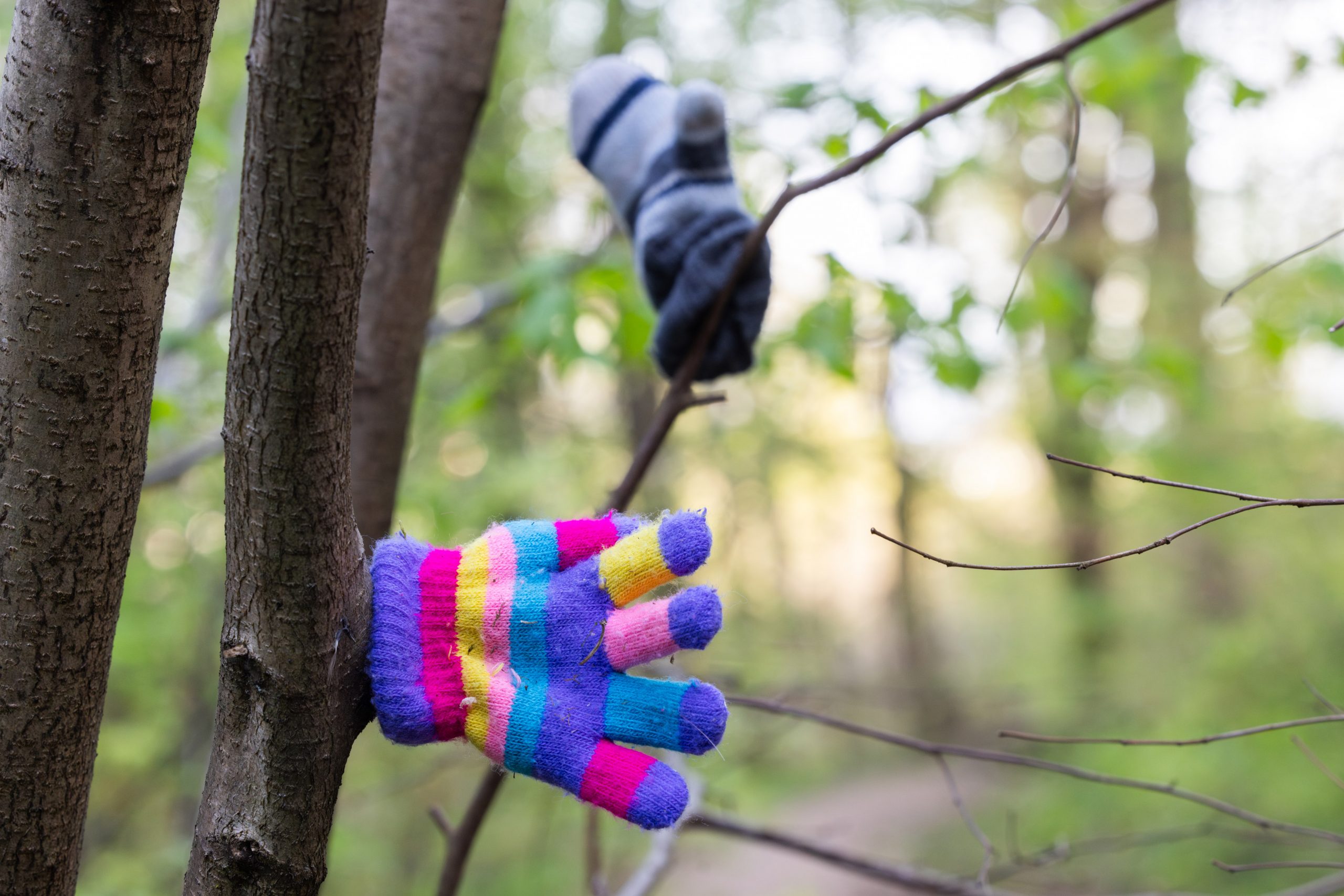
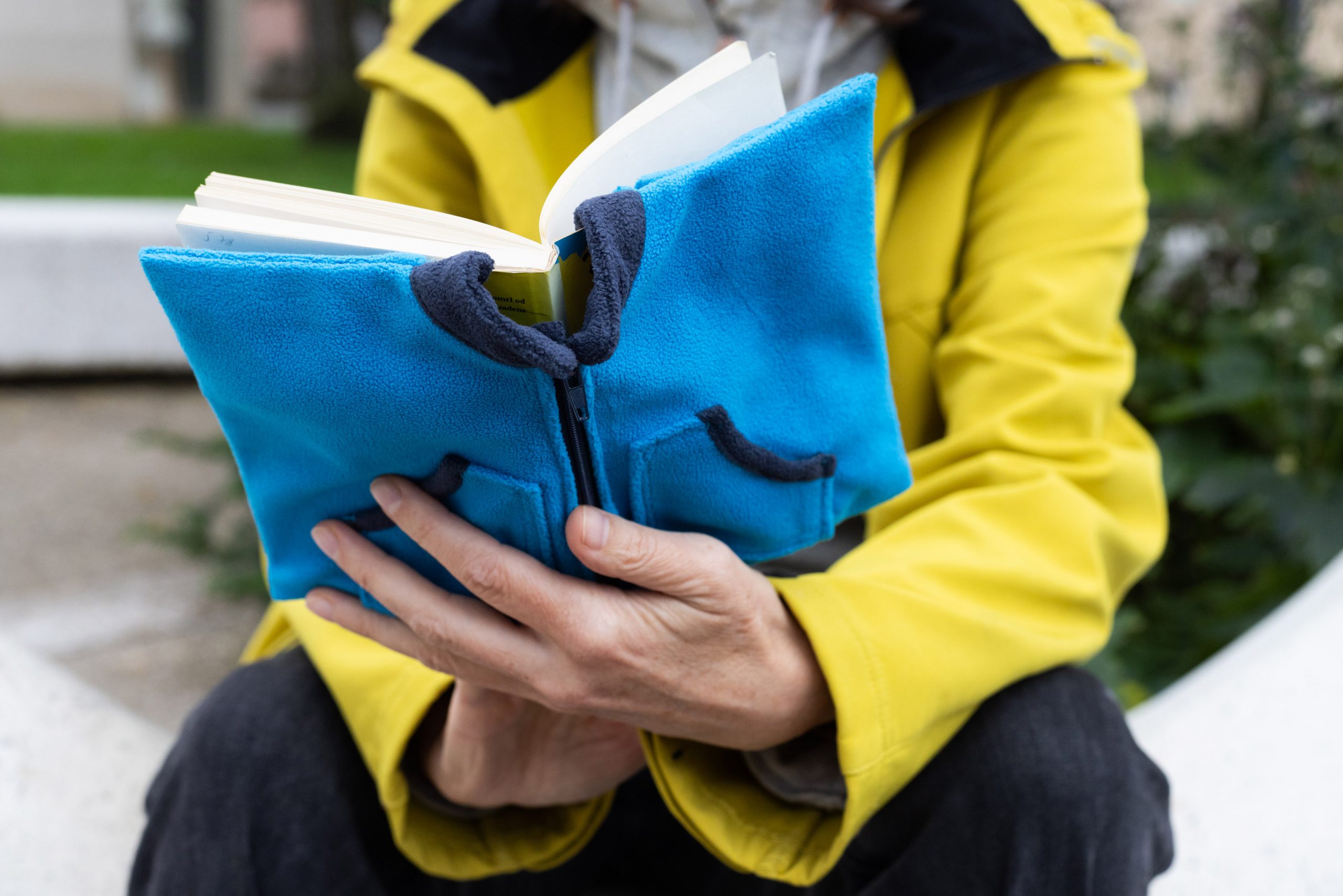
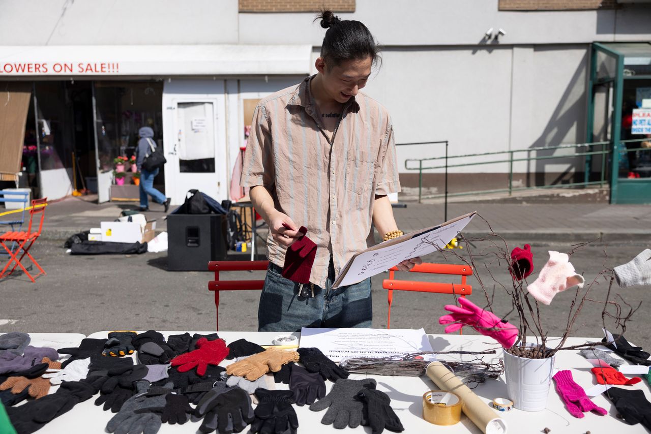
V nedeljo, 18. 5. 2025, je v ateljeju Marije Mojce Pungerčar v Švicariji potekala njena umetniška akcija Sporočilo izgubljeni polovici, v kateri je sodelovalo 40 obiskovalcev.
Štirideset rokavic brez para so obiskovalci z bucikami, nitjo in šivanko predelali v raznovrstne emoji-je. Dogodek je bil del prireditve Dan odprtih vrat ateljejev.
So vam po minuli zimi ostale rokavice brez para, s katerimi nimate kaj početi? Prinesite jih v nedeljo, 18. 5. 2025 v Švicarijo, na Dan odprtih vrat ateljejev, kjer boste lahko sodelovali pri nastajanju umetniškega projekta Sporočilo izgubljeni polovici umetnice Marije Mojce Pungerčar.
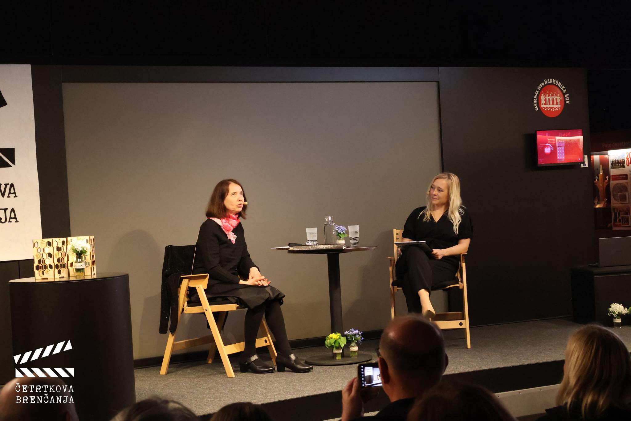
V Muzeju Lojzeta Slaka in Toneta Pavčka je v četrtek, 24. aprila 2025 potekal pogovor z umetnico Marijo Mojca Pungerčar. Dogodek je organiziralo Kulturno društvo Četrtkova brenčanja. more »
V predlogih se zavzemamo za upoštevanje karierne dinamike samozaposlenih kulturnih ustvarjalcev, za zvišanje plačnih razredov za vse kulturno-umetniške poklice, za ustreznejše plačne razrede za nekatere poklice in za definiranje razstavnine.
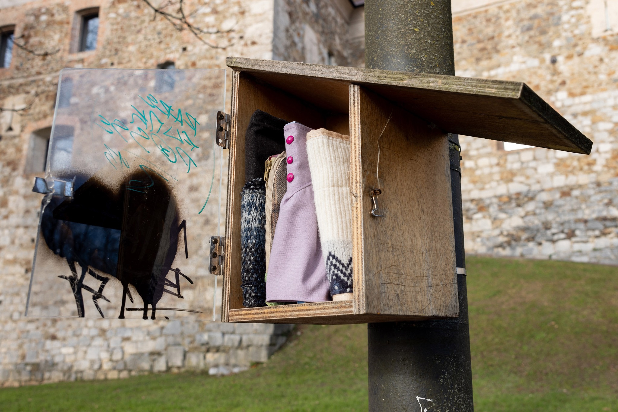
To zimo se je petdeset knjig vselilo v knjigobežnice v ljubljanskem Botaničnem vrtu, v Centru za ponovno uporabo na Povšetovi, na ljubljanskem gradu, v Kinodvoru, v avlah Ministrstva za kulturo, Narodnega muzeja in Filozofske fakultete ter v menzo viškega Interšpara. Nekaj knjig pa je dobilo začasni dom v knjigobežnici pred Muzejem Lojzeta Slaka in Toneta Pavčka v Mirni Peči.
Novičnik za samozaposlene v kulturi vabi samozaposlene ustvarjalce v kulturi k prijavam na brezplačno delavnico ODDAJA LETNIH DAVČNIH OBRAčUNOV, ki bo v četrtek, 20. februarja 2025 v Vetrinjskem dvoru v Mariboru.
Delavnica bo potekala od 11.00 – 14.00 ure na naslovu Vetrinjska ulica 30.
Dejavnosti KUD Trivia lahko podprete z donacijo 1 % dohodnine. Veseli bomo vaše podpore!
V ta namen izpolnite obrazec in vanj vpišete naziv Kulturno umetniško društvo Trivia in davčno številko 48686743. Obrazec pošljete na najbližjo davčno izpostavo do 31. decembra 2024. Lahko ga oddate tudi elektronsko preko eDavkov.more »
MGLC Švicarija, Ljubljana, Atelje M2.2, nedelja 1. 12. 2024od 12.00 h - 18.00h
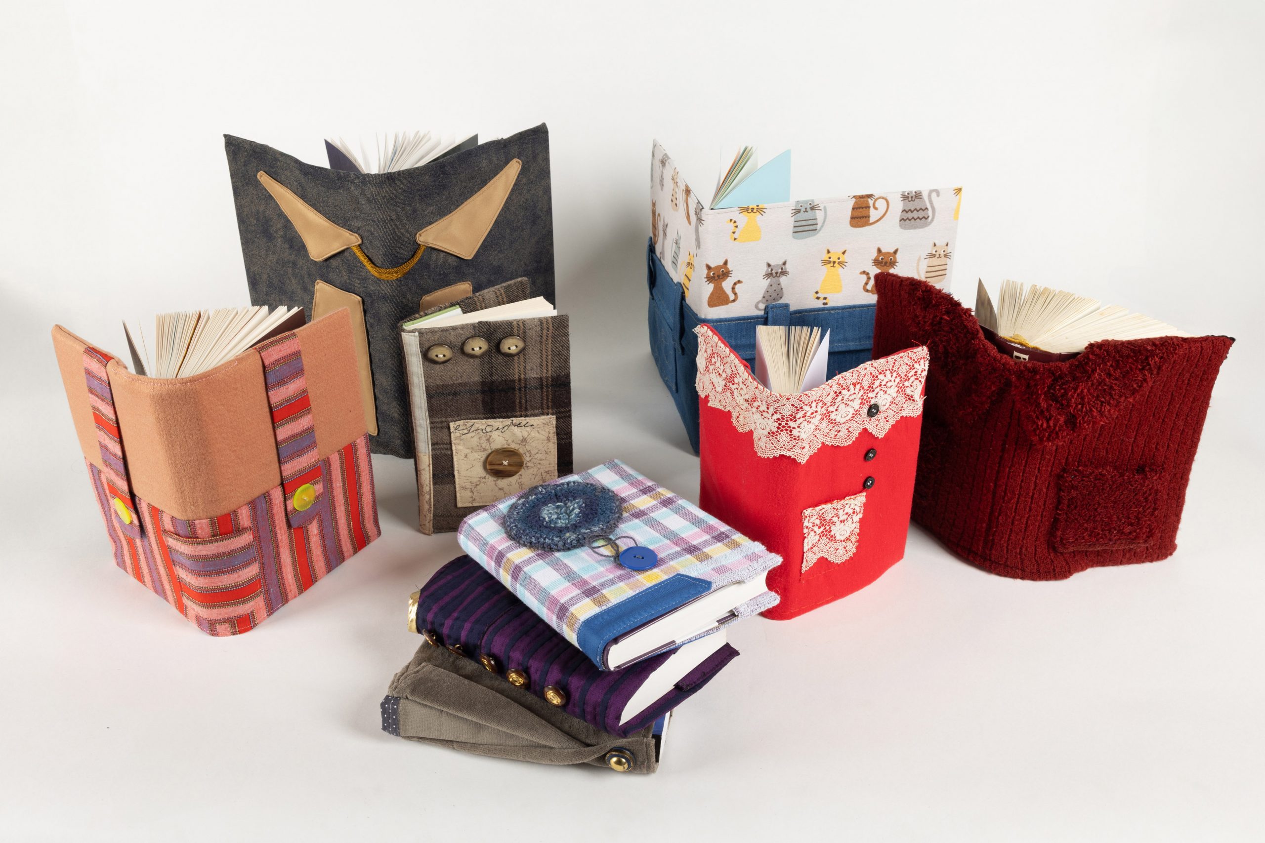
Na razstavi bo predstavljenih 50 knjig, ki so dobila oblačila v okviru projekta Knjige, ali vas zebe?. Celotna kolekcija oblečenih knjig bo v Švicariji na ogled samo v nedeljo, zato ne zamudite razstave!more »
KUD Trivia / Novičnik za samozaposlene v kulturi je poslal Ministrstvu za kulturo svoje predloge v odziv na javno obravnavo predloga Zakona o spremembah in dopolnitvah Zakona o uresničevanju javnega interesa za kulturo (ZUJIK - I). more »
Za sodelovanje pri umetniškem projektu Marije Mojce Pungerčar vabimo k donacijam knjig, ki bodo v okviru projekta zaokrožile v brezplačni izmenjavi knjig. Iščemo tudi šiviljske sodelavke.
Novičnik za samozaposlene v kulturi je na Ministrstvo za kulturo poslal pobudo o uskladitvi dnevnega nadomestila za čas zadržanosti od dela zaradi bolezni ter predloge za izboljšavo dnevnega nadomestila v korist samozaposlenih v kulturi. ...more »
Novičnik za samozaposlene v kulturi je na Ministrstvo za kulturo poslal pobudo o uskladitvi dnevnega nadomestila za čas zadržanosti od dela zaradi bolezni ter predloge za izboljšavo dnevnega nadomestila v korist samozaposlenih v kulturi. ...more »
Preberite si odgovore na pogosto zastavljena vprašanja o Novičniku, oglejte si primerek kazala in se prepričajte, kako so naročniki zadovoljni z Novičnikom! ...more »
Trivia Records Zapisi
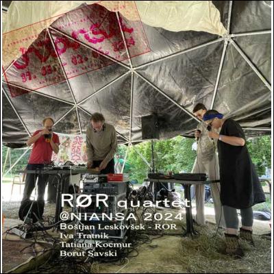
Recorded live at NIANSA2k24 festival at Rakov Škocjan, Slovenia on June 2nd 2024. ROR QUARTET were: Boštjan Leskovšek - ROR, Iva Tratnik, Tatiana Kocmur, Borut Savski. This was a group built around sound artist, poet, photographer and friend Boštjan Leskovšek. This was his last public appearance.
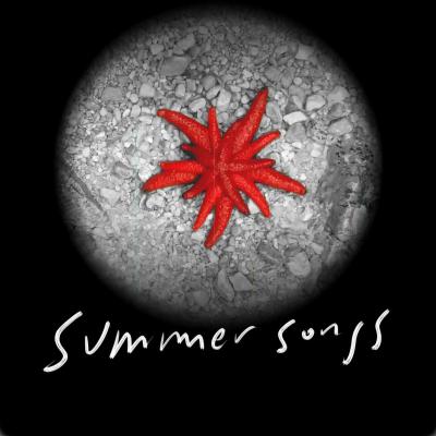
Summer Songs, drugi projekt dua The Silent Movies, je umetniško okolje, sestavljeno iz vrste virov vizualnih, zvočnih in verbalnih informacij, ki so med seboj odvisni. Deluje kot neskončen koncert, na katerem video instalacija, sestavljena iz serije nedavnih nemih filmov Francisca Tomsicha, zagotavlja grobo gradivo, rdeče niti in digitalne podatke zvočnemu ekosistemu Boruta Savskega..
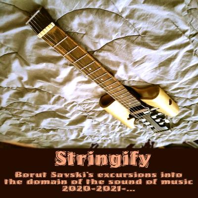
Lately i am acquiring some finger dexterity again. The victims are some relatively newly developed instruments (turboguitars, turboflutes and cirkulinos). Here is a selection of cutouts from various live situations - mostly as parts of Cirkulacija 2 program - from 2020 onwards.
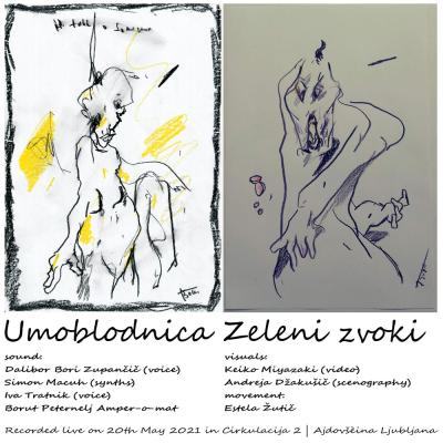
Celjska interdisciplinarna impro zasedba s projektnim imenom Umoblodnica v sestavi: Iva Tratnik, Andreja Džakušič, Keiko Miyazaki, Estela Žutić, Simon Macuh, Dalibor Bori Zupančič, Borut Peternelj – Amper-o-mat. Posnetek nastopa 20. maja 2021 Cirkulaciji 2 | podhod Ajdovščina.
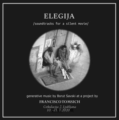
Generative algorithmic composition excerpts based on realtime video data for Francisco Tomsich "ELEGIJA | ELEGY" video installation presented from 10th to 21st July 2020 at Cirkulacija 2 Ljubljana Slovenia. Elegija (Elegy) is a mournful song performed by ensemble of video installations, sculptures and sound installation – made specifically for Cirkulacija 2 premises in Ajdovščina subway.
 V nedeljo, 17. maja 2026 bo Marija Mojca Pungerčar v svojem ateljeju s priložno razstavo predstavila gostovanje projekta Sporočilo izgubljeni polovici v New Yorku. Predstavitev bo trajala od 18.00–20.00 ure.